
This story takes place my sophomore year as “Chief Engineer” in REV, during the Fall 2017 – Spring 2018 semester.
Our major role on the ELEC side was figuring out how to build a motor controller for two 48 Volt Brush DC motor controllers.
Previous work:
Damien, Clark, and Irene had begun building a motor control last year for REV. However it was quite complicated, and this year I don’t think to start out any of us (except Irene) had the ELEC expertise to jump into this controller right away.
I thought up this crazy 3-part idea for the motor controller. The first would begin being incredibly simple, and the following controllers would increase in complexity, robustness, and features.
1: Simple Switch
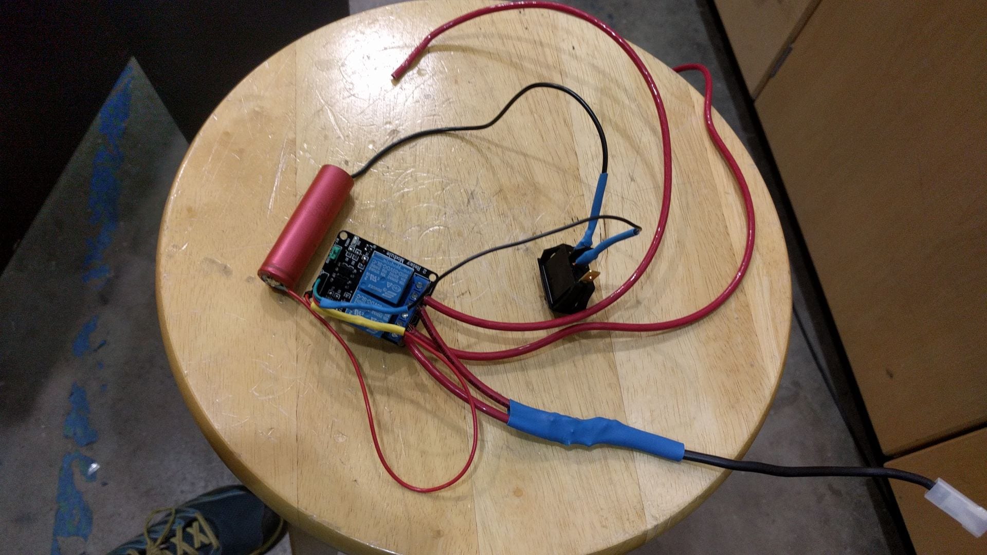
The first controller we built as part of this was a simple relay connected to a battery. Since the 48 V battery connected through a relay to the motor directly would be a disaster, we used some 12V Lead-acid batteries we found laying around.
In effect, this meant the driver only had a on/off switch to start the car and go at a constant speed (low speed).
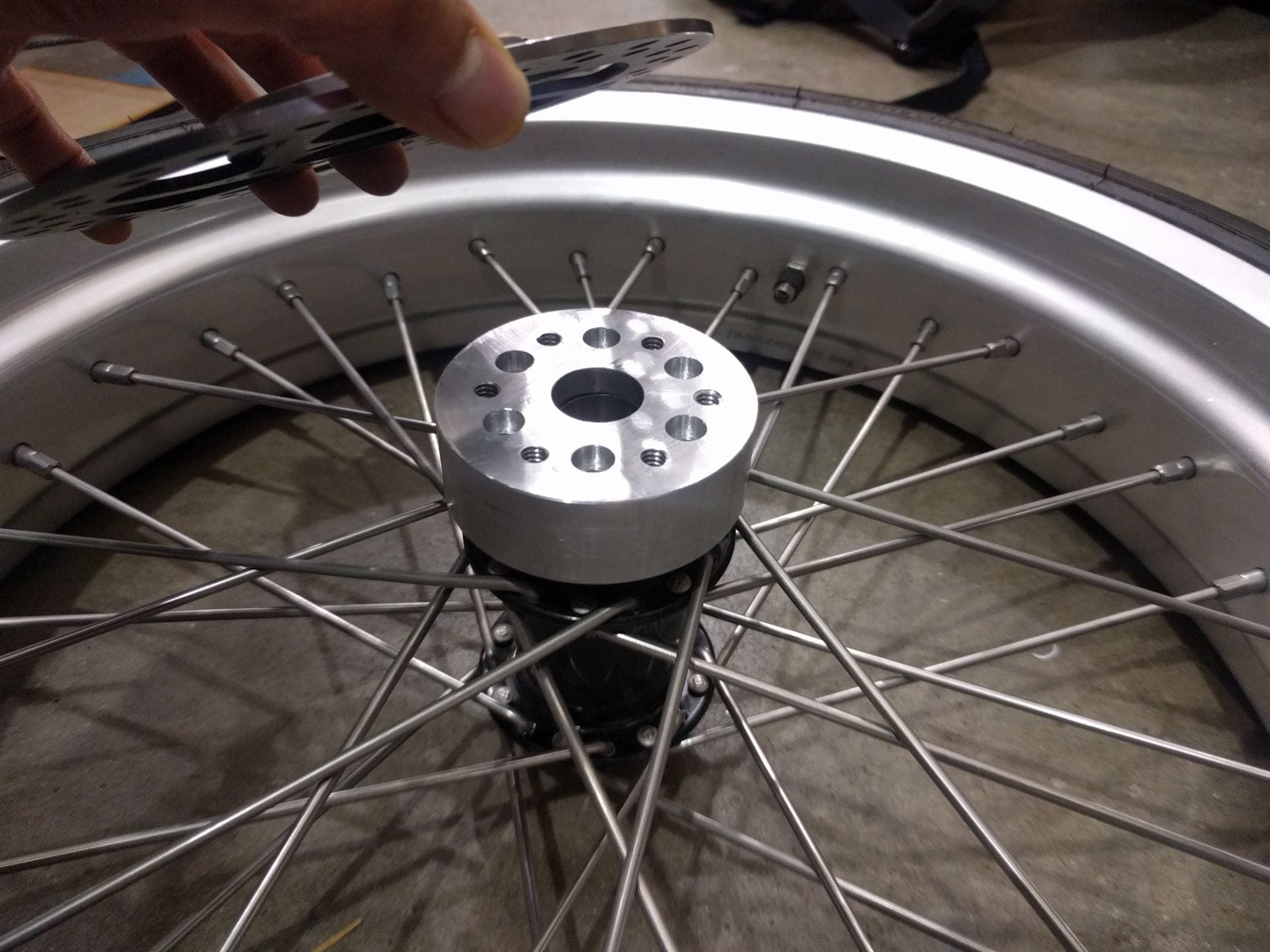
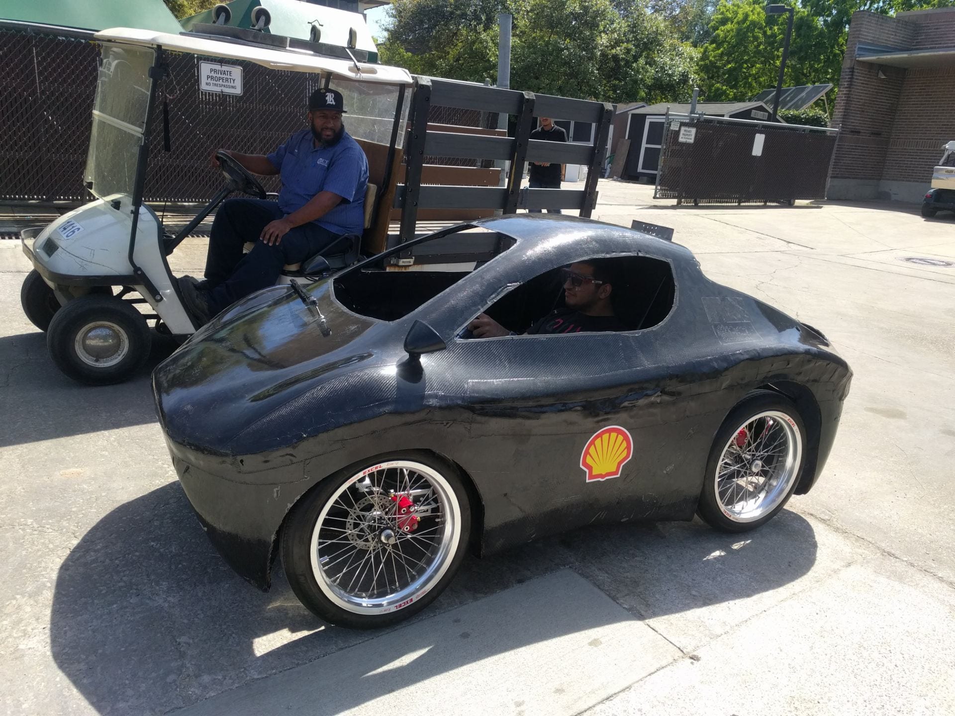
This circuit was incredibly simple and took us under 2 hours to put together. We worked with the Mech team to put the wheels on the car and we were actually able to start driving the car down the street! It was very slow though and the wheels started to fall out (the shafts needed tapered bearings so the wheel wouldn’t move side to side).
2: MOSFETs
After this simple relay circuit, we started to think of ways in which we could modulate the speed of the motor, and also go faster and implement the deadly 48V battery we had. In this controller, our idea was to connect the Motor to the battery through some FETs and power the gates of the MOSFETs directly through an Arduino. However, we didn’t know that the FETs needed more power to turn on. This resulted in having pretty high ON-resistances from the FETs and eventually overheating and failure issues.
However, we were able to spin some PCB boards and improve our skills through this next iteration of the motor controller. The car would also seem to work fine when we jacked it up and just observed the wheels spinning, but after we put it down and tried to run it on the ground, the motor controller would fail pretty quickly.
2.1: MOSFETs with a drive
We now realized that we couldn’t power the gate of the MOSFETs directly through an Arduino. This time we decided to implement a gate driver chip in between. I think “Gate Driver” also sounds really cool. It sounds like we’re turbo-boosting our car.
The problem with the gate driver was that we had no way of sensing current and therefore had an open-loop system. When the driver would step on the accelerator, it would send too much power to the motors and they would fail. We needed a system to control how much power to send to the motors. We needed a current limit.
3: Full H-Bridge driver
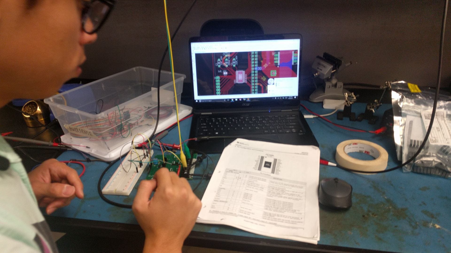
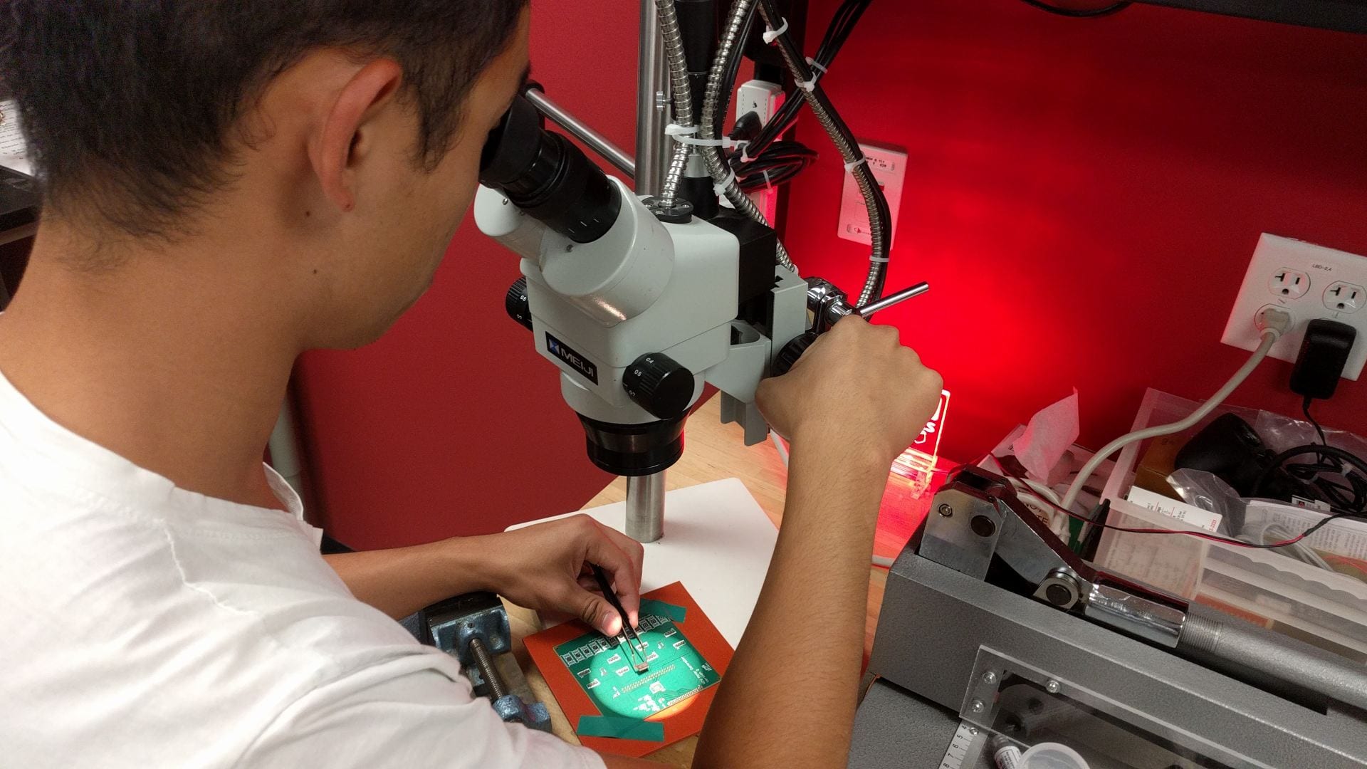
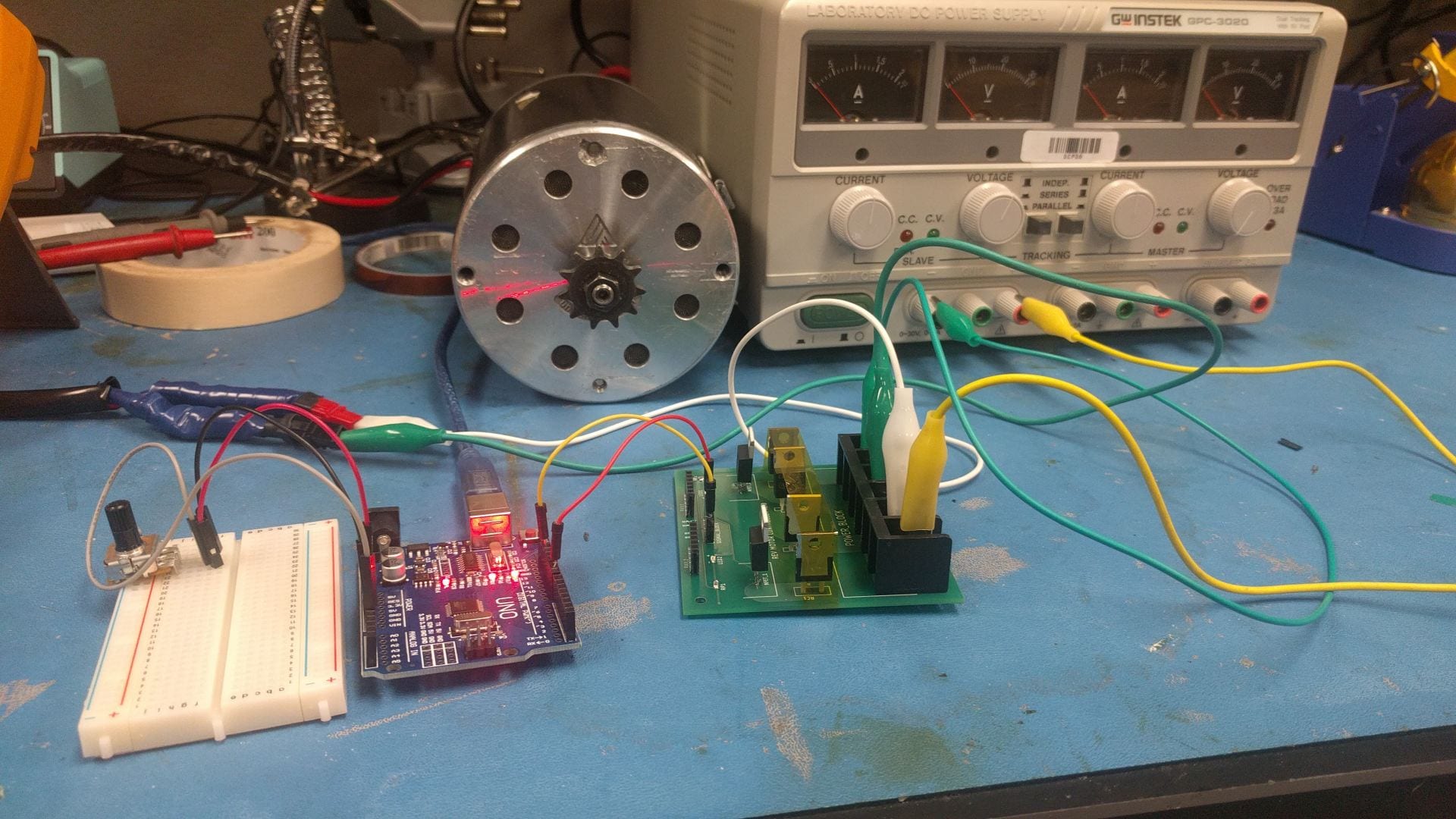
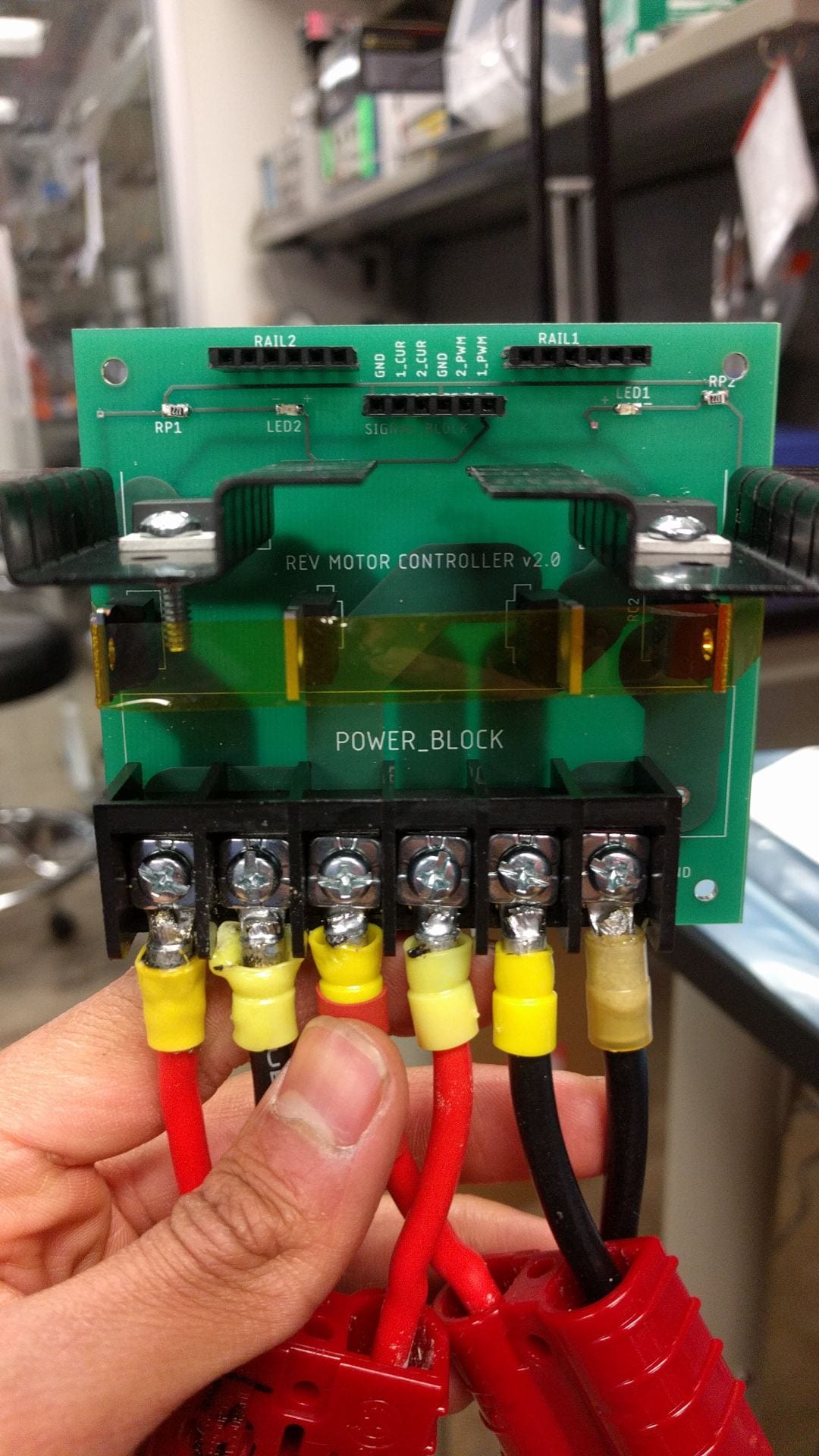
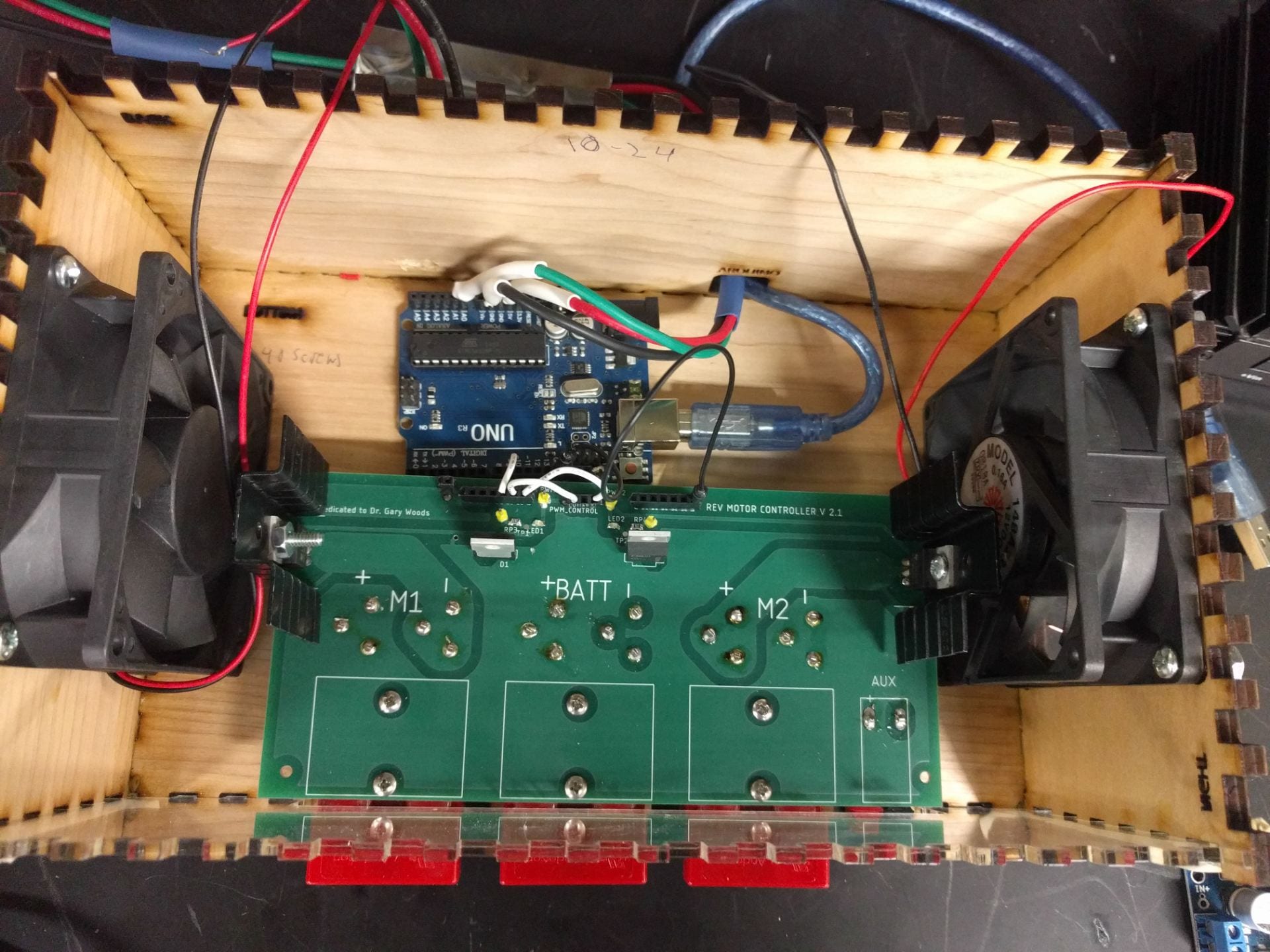
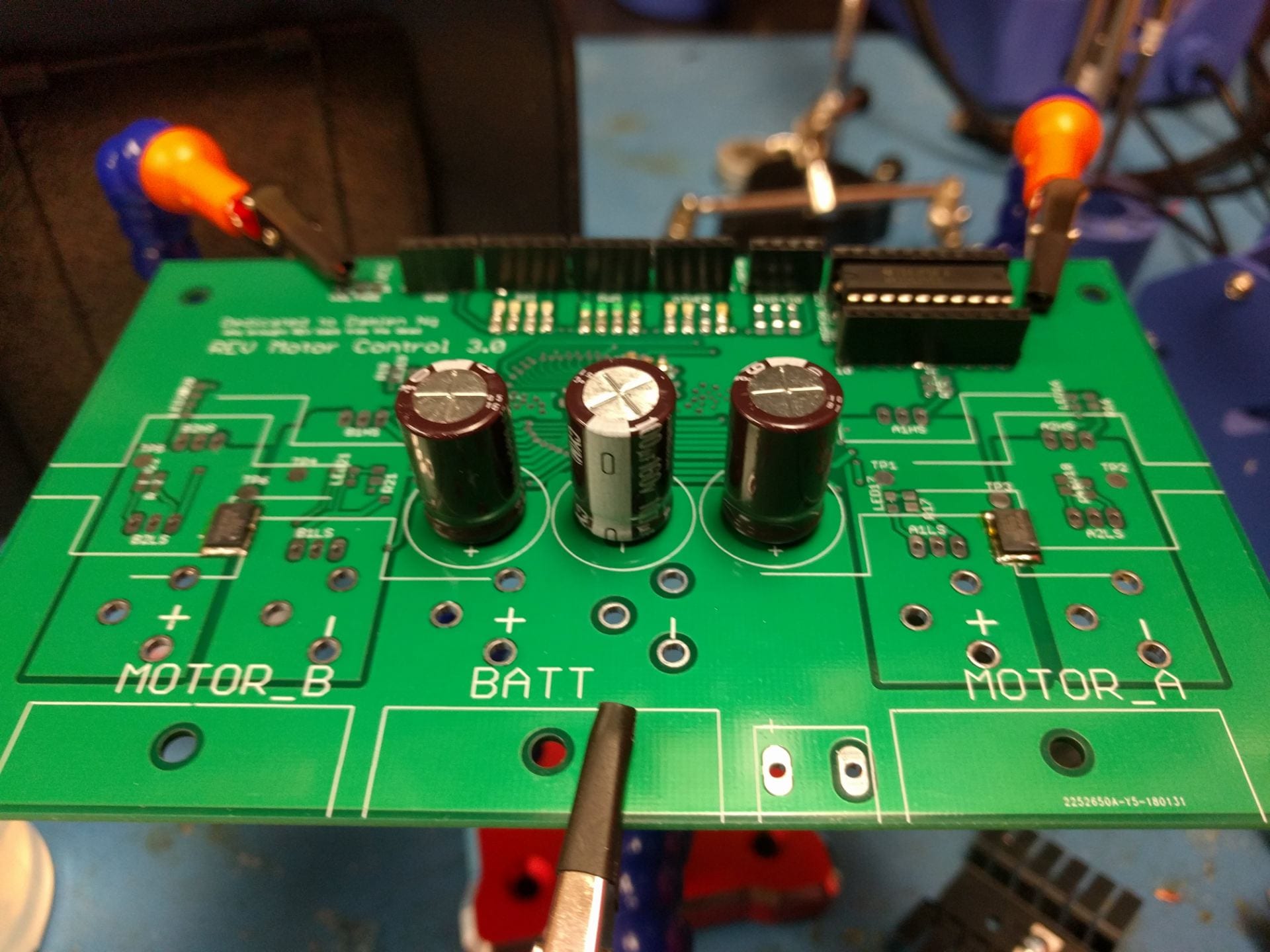
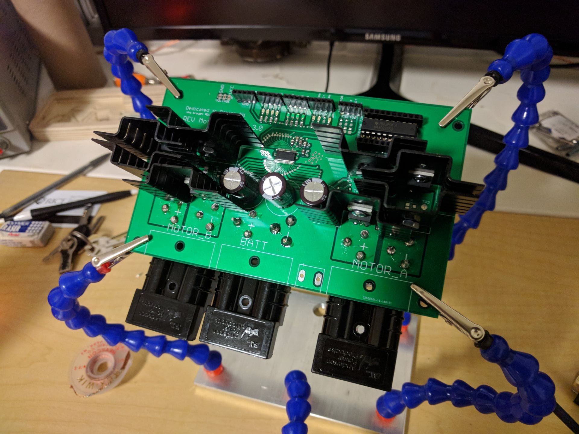
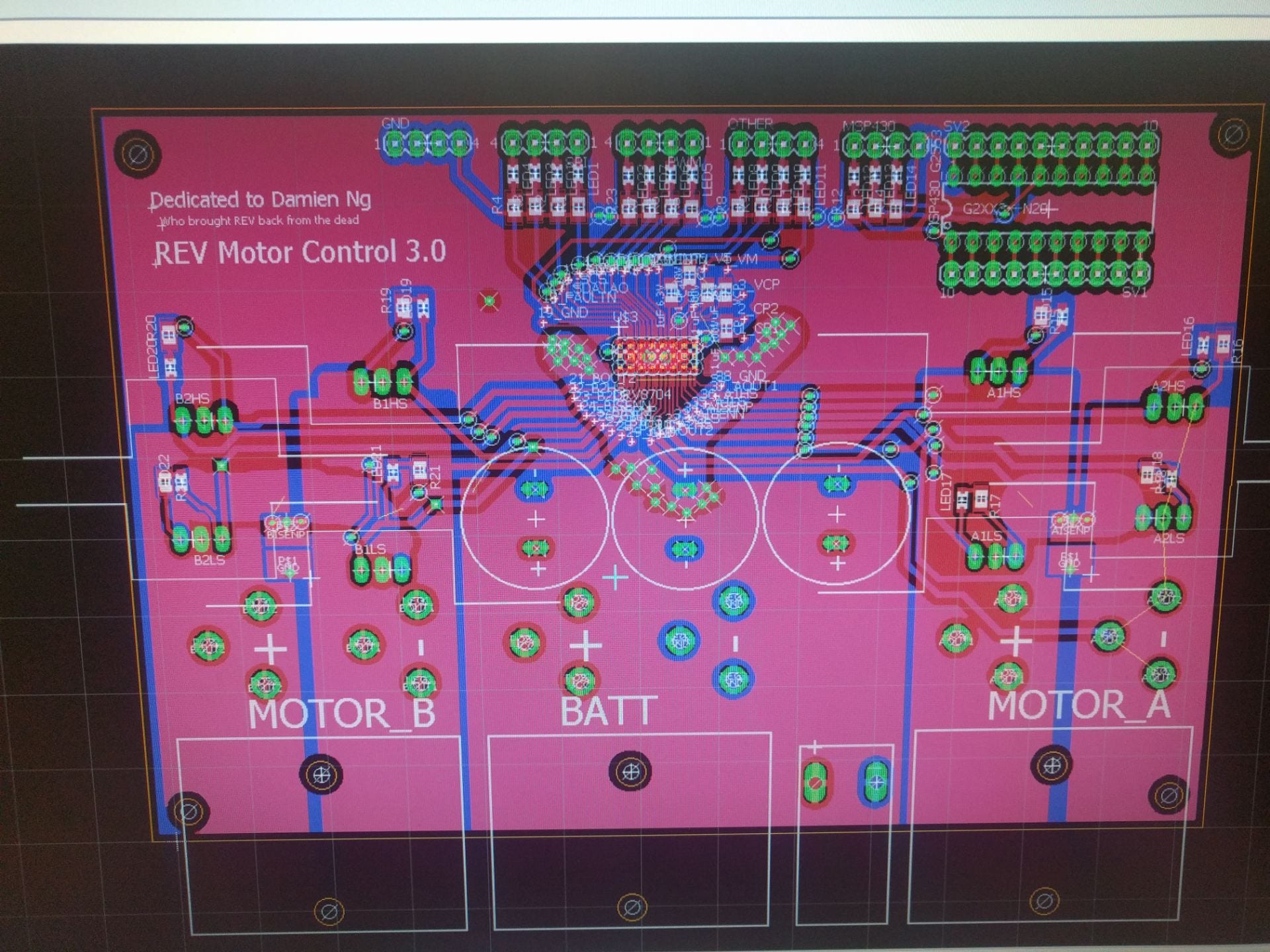
The way for us to implement a current-limit would be using an intelligent motor control driver chip, like the one that Damien Clark and Irene had used in the year brefore. With the experience we had aquired by this point, we thought we ewre ready to build a full H-Bridge driver controller and get serious for competition. We built around the DRV8704 dual H-bridge driver chip from TI. We spent hours and hours reading the datasheet, designing the printed circuit boards, writing thousands of lines of code, and soldering all the SMD components together.
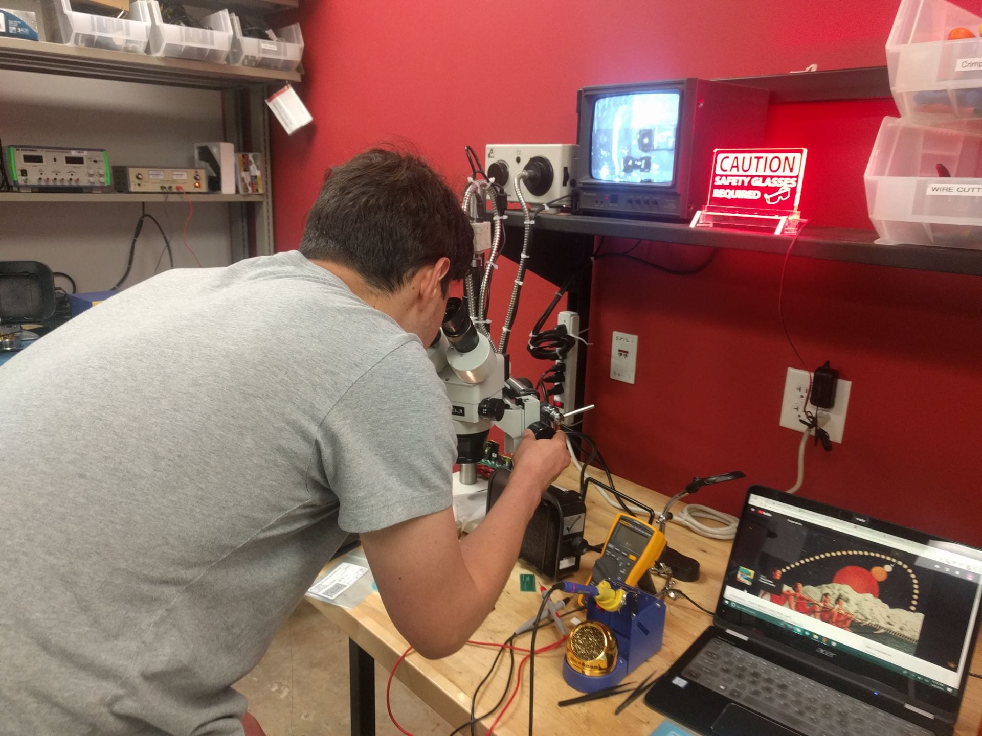
I remember when I got the first PCB board back and soldered on the chip and gave it power. I saw an LED light up from an indicator pin on the gate driver, and I was delighted. This was one of the best ELEC moments for me so far. Just a little LED meant so much for me. I also remember working o a saturday night with Louis and Irene, and the first time we were able to send and receive SPI communication to the chip, using a digital logic analyzer to see what was going on. Reading those hexadecimal digits from the registers and seeing them change made us so excited and happy.
We put a lot of effort trying to get this to work, and for most of us was the best ELEC work we had done up to that point. This was one of the hardest things I’ve ever done in my life. It started to become all-nighter after all-nighter in the OEDK ELEC lab.

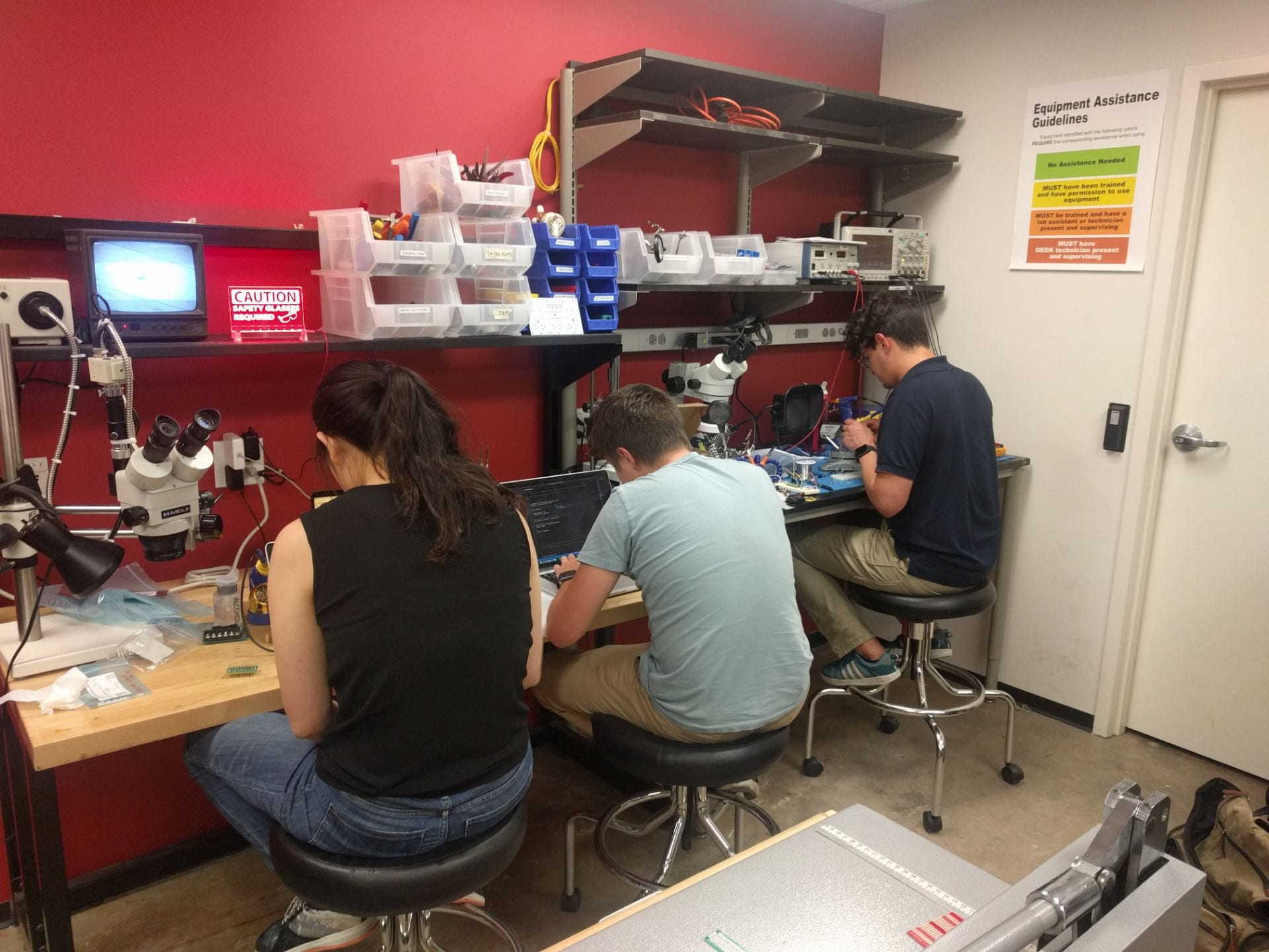
So we put this motor controller together over several late nights in the OEDK. Mau wrote a ton of code for it to function properly, and we were able to access the specific registers inside of the gate driver and adjust the different drive parameters.
But after all this, we had a strange problem. We were running closed loop control for current, and under most circumstances, this wasn’t a problem. But in one case, whenever the driver would release the accelerator and let the speed decrease, this controller would go crazy and start oscillating at several MHz and with like 40V peak to peak, in many pins. This caused our teeny little gate driver chip to blow up several times. It was only under this strange scenario. We tried tweaking the gate drive parameters but it kept on happening. We determined this wasn’t a very robust controller.
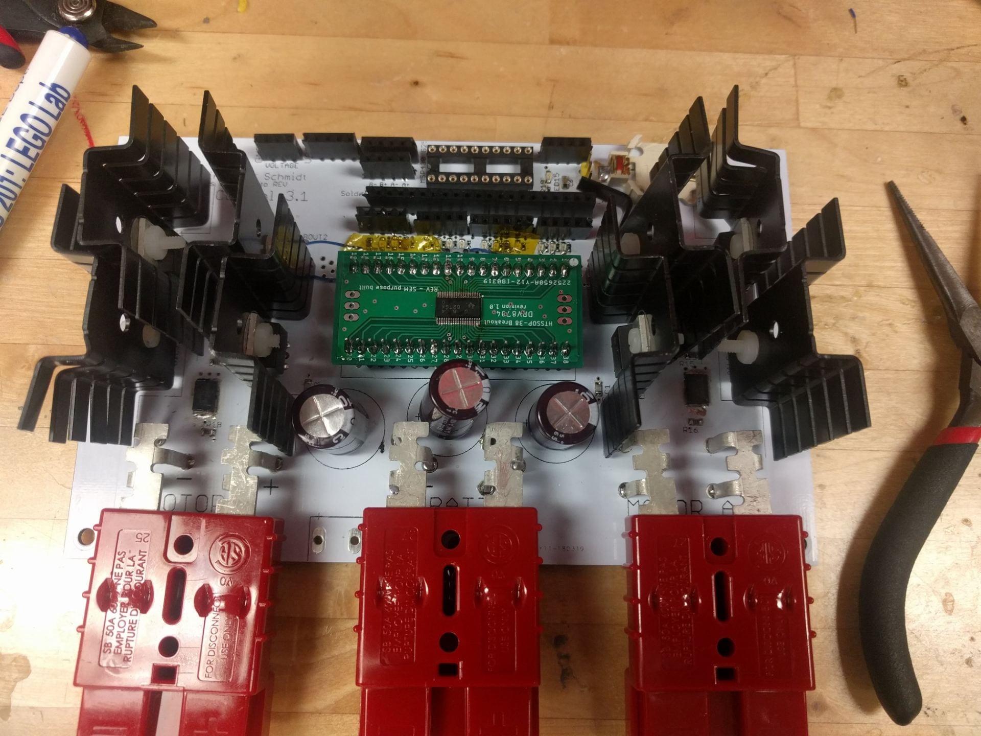
In foresight, it might’ve been that the ceramic bypass capcitors were not close enough to the actual rails of the gate driver chip. This teeny gate driver chip was very difficult to solder, so I decided to build a breakout board of sorts for the gate driver. And the bypass capacitors were placed on the main motherboard. This might’ve been the problem, but we didn’t investigate enough to see if it truly was.
Testing:
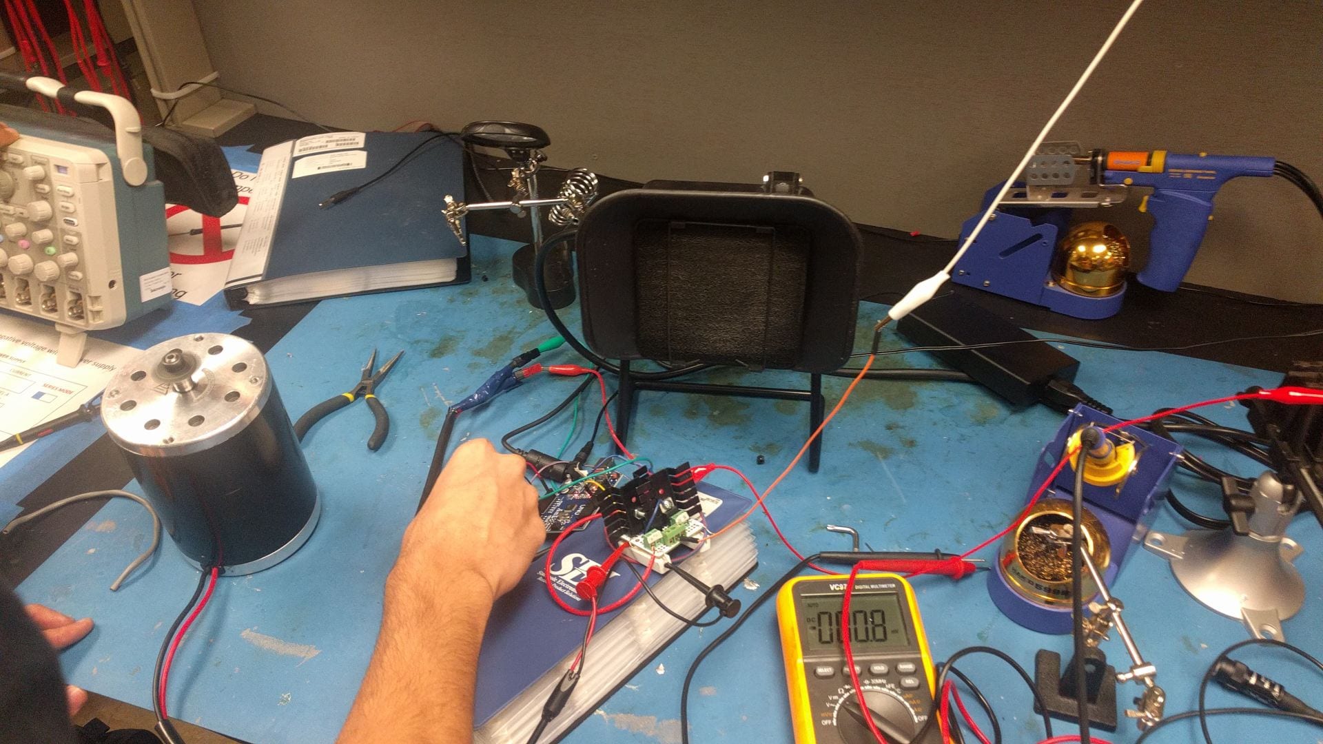
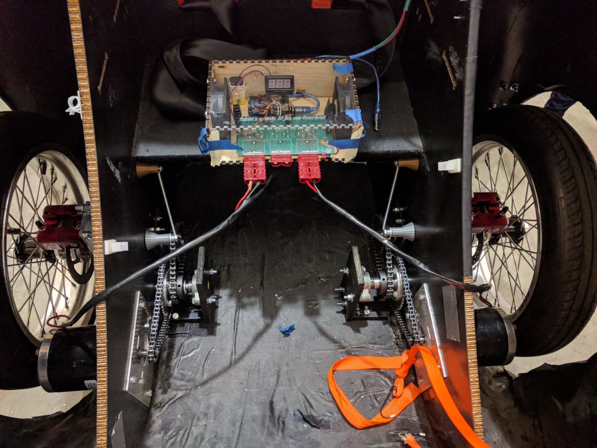
During the testing of this, we decided to build a testing contraption that could simulate putting our motor controller under a load. We brought in a Mechanical Engineering friend (Caz Smith) as a contractor to help with this. We linked 2 motors mechanically through a chain and loaded the second motor through a bunch of heating coils that acted as a resistor bank.
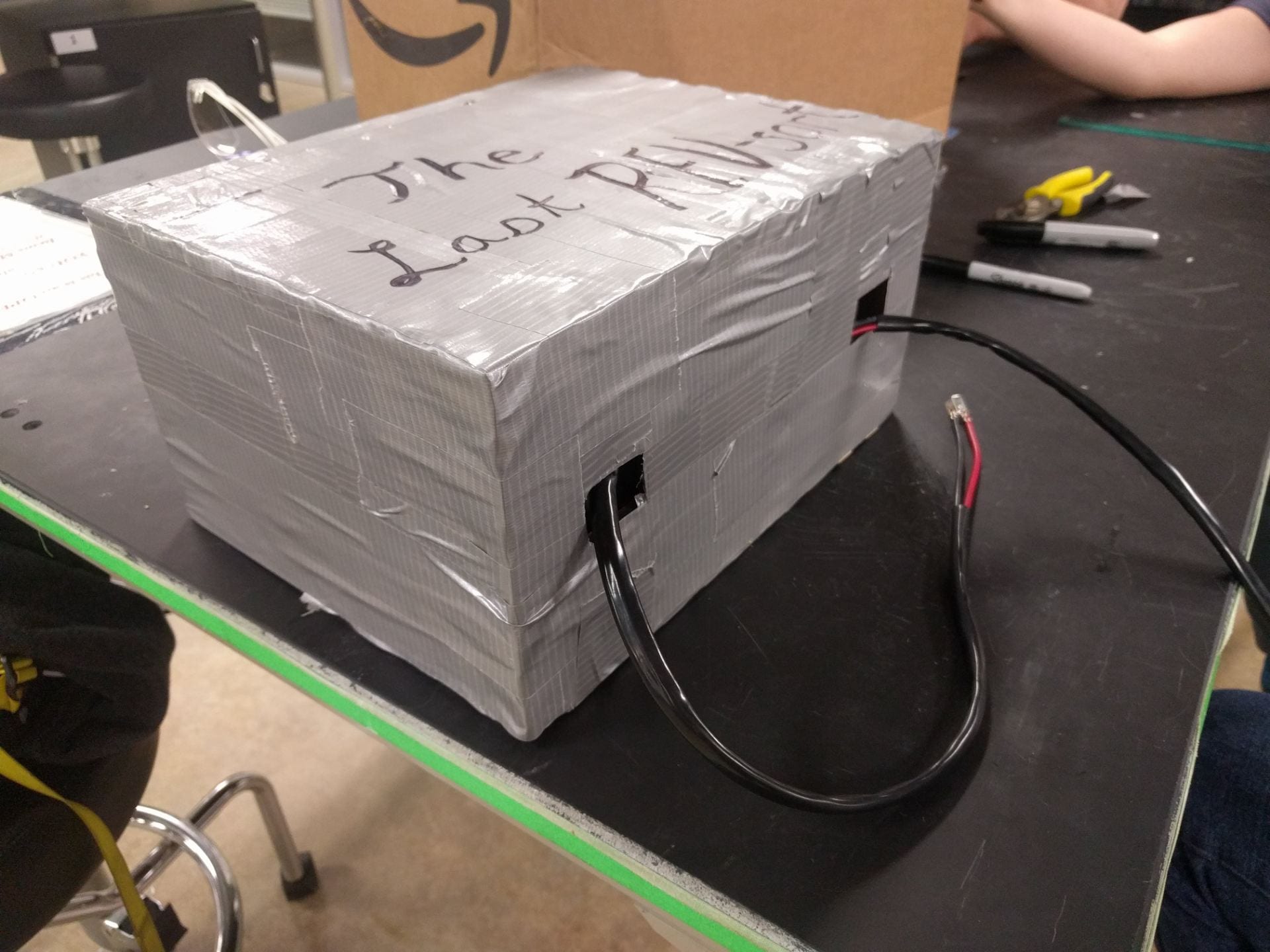
When we shipped the car off to competition, we shipped off 2 of the motors we had. the other 2 motors we had left with us ended up having different sprockets and one of them was faulty and we couldn’t change out the sprocket. We also didn’t have the right chain for that sprocket. This meant the 2 motors we had ended up with different size sprockets and the chain didn’t fit adequately. In fear of having the chain bust open and injure someone severely, we built a box and duct taped everything around it in case this happened. This resulted in this mysterious looking box below.
Countdown:
It was getting pretty close to the competition date and we had to decide what we were going to do. We decided to revert back to the second generation gate driver chip and attempt to make a new board that was more robust. We packed up the car inside a wooden box and shipped it off to Sonoma.
The night before flying out to competition Irene and I met in the ELEC lab and we tested this final second edition motor controller. We had built it more robustly and were able to send 20+ Amps of current to it continously. We were confident that even though this was an open-loop control, it would still be strong enough to power our car.
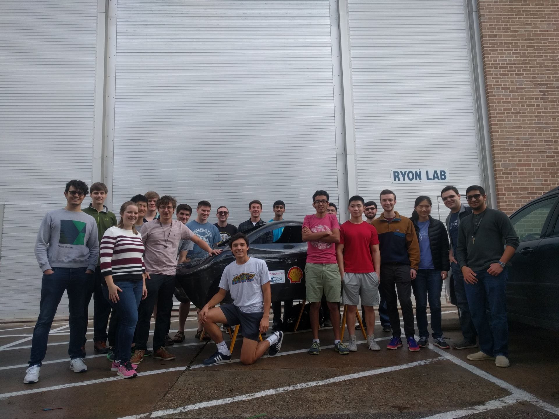
Overall the year had been pretty crazy. Our team had learned a ton of new things about power electronics and Electrical Engineering and had now made a lot of mistakes along the way.
We were now on a flight and ready to get our car out to competition.