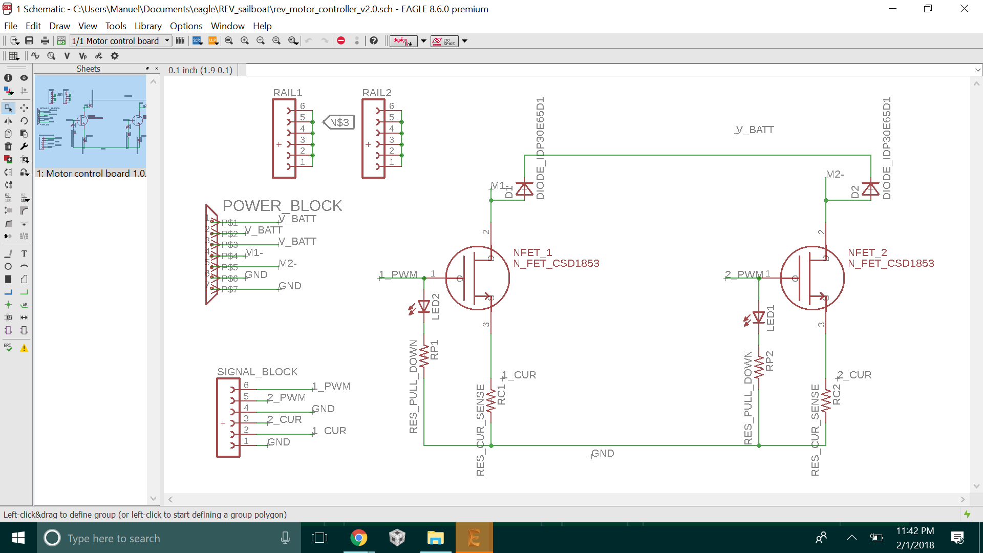
This is the second motor controller I’ve built for Rice Electric Vehicle. It works under a pretty simple principle. Each motor is connected through a MOSFET and current sense resistor to ground.
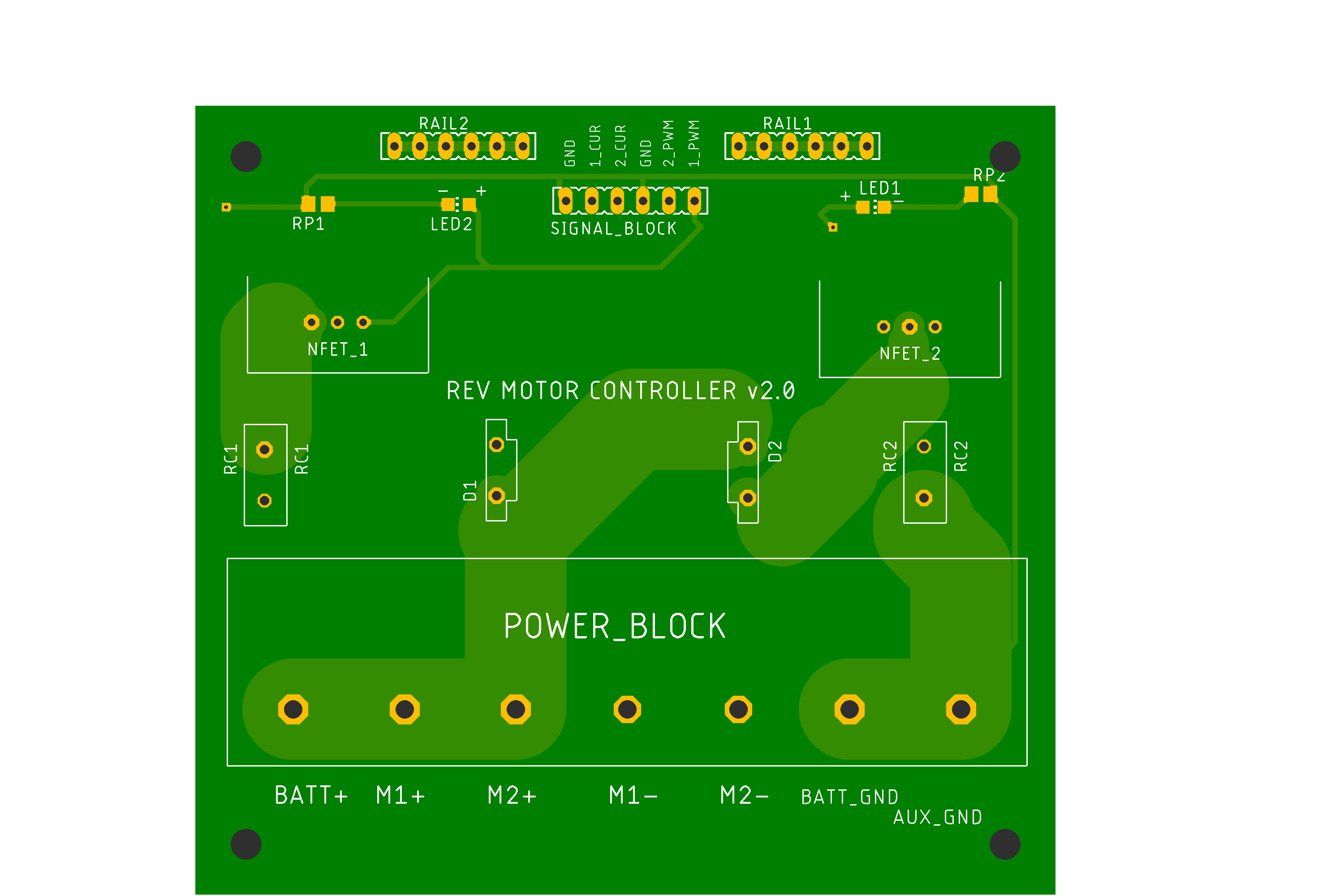
Below is the board that was designed from this schematic. I attempted to use thicker traces that could handle more current.
Drawbacks
- Current limiting resistor caused a large voltage drop, which lowered the gate to source voltage of the MOSFET. There was no feedback going to the drive of the MOSFETs. This caused the resistance of the MOSFET go up at peak current draw (acceleration), which made our MOSFETs explode. They lit up like firecrackers (not really). Even though the resistor was 100 mOhm, this caused problems.
- No ground or VCC plane included. This resulted in unnecessary traces and not as much heat dissipation as there could be.
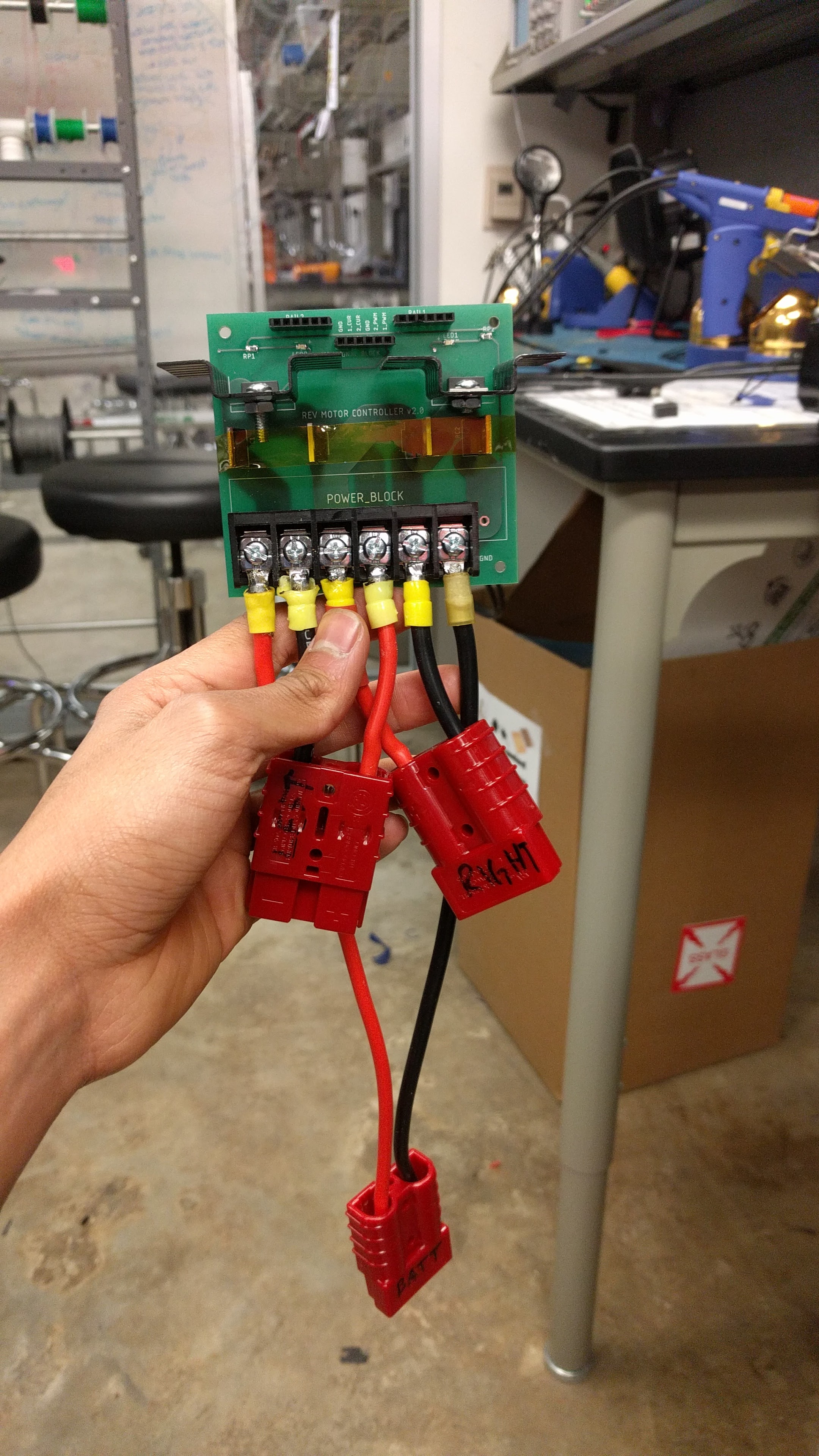
- Terminal block sounds nice, but we had to crimp connectors and solder them to SB50 power plugs which ended up looking messy
-

Motor Controller Board 2.0